I/O-Modules
Fox Series
DeviceNet - Coupler
Product Description
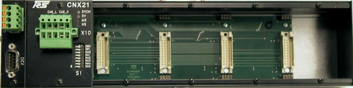
The CNX21 Base
Module is the basis of the digital input/output Submodules for operation
in the DeviceNet. Depending on the application, the four modules can be
configured as inputs or outputs with a wide range of different
modules.
Power Supply
You connect the power supply for the control logic via the four-pin connector terminal X10 on the upper left side of the module. The power can be either used from the DeviceNet™ network or from a separate power supply.
| Pin | Signal | Description |
| 1 | V- | GND control voltage supply |
| 2 | CAN_L | CAN Data Low |
| 3 | Shield | Shield |
| 4 | CAN_H | CAN Data High |
| 5 | V+ | +24 V control voltage supply |
Four LED's provide information about the status of the module:
Module-Status (MS LED)
| LED | Description |
| OFF | No Power - Module (Connector X10) |
| Green | Bridge OK |
| Red | Wrong Data Size |
Network-Status (NS LED)
| LED | Description |
| OFF | No Power - Module (Connector X10) |
| Flashing Green | Not online, no connection to master established |
| Solid Green | online, connected to master |
| Flashing Red | Timeout, I/O connection |
| Solid Red | No connection to Master, Duplicate MAC-ID or bus off |
Power LED DeviceNet™ (5 VCN)
| LED | Description |
| OFF | No Power - DeviceNet™ (V+ & V-) |
| Orange | Power OK - DeviceNet™ |
Power LED Base Module (5 V)
| LED | Description |
| OFF | No Power - Module (Connector X10) |
| Orange | Power OK - Module |
DeviceNet™ Address
NA0 - NA5 set the DeviceNet™
node number (0-63) of the module. The node number is binary coded. Lowest
bit0 is switch NA0 and highest bit is NA5.
Example: Node 6 NA1 and NA2 ON all other (NA0, NA3, NA4, NA5) remain OFF.
DeviceNet™ Baudrate
DR0 and DR1 set the baud rate of the module.
Example:
125KB DR0 = OFF and DR1 = OFF
250KB DR0 = ON and DR1 = OFF
500KB DR0 = OFF and DR1 = ON
500KB DR0 = ON and DR1 = ON
Assembly
You mount the DeviceNet™ base module off-center of the machine or in the control cabinet by simply fastening it to a device mounting DIN rail.
Technical
Data
| Inputs/Outputs |
Max.of 64
digital I/Os or. max of 16 Analog I/Os , or a mixture of both via
up to four galvanically decoupled submodules ( max. 4 submodules
), divided into four ports that can be fitted byte-by-byte with
input or output modules (MDI-8,MDO-8 etc.). |
|
Input Specifications |
Refer to input
modules for CNX21 |
|
Output
Specifications |
Refer to output
modules for CNX21 |
|
Output Monitoring |
Watchdog circuit |
|
Connections |
5 pole DeviceNet
plug ( Phoenix Contact ) |
|
Supply Voltage |
24 VDC (±
20%) |
|
Current Consumption |
approx. 0.1 A
(without submodules) |
|
Housing |
closed, can be screw-mounted on a device mounting rail complying with DIN EN 50022, 50035 |
|
Dimensions (W x H x
D) |
CNX21:
315 * 76 * 68 mm |
|
Weight |
approx.. 750 g |
|
Operating
Temperature |
±0..+55 °C |
|
Storage Temperature |
-20..+70 °C |
back | Fieldbus Terminals | Download | Home
Copyright © 2000 TRS
Fieldbus Systems, Inc. All rights reserved.
Revised: August 08, 2000
.