I/O-Modules
Fox Series
MAI-4, Analog Input Sub
module
The MAI-4 input module is a submodule, which is galvanically decoupled by means of optocouplers, for the base module. It provides four analog inputs.
For operation in the I/O system, you can
install up to four MAI-4s in the four slots of a base module. This makes
possible a maximum of 16 outputs per
base module. In addition, you can combine
MAI-4s with different modules, e.g. digital outputs.
Two variants of the MAI-4 module can be supplied:
- MAI-4 12 12 -bit resolution
-
MAI-4 16 16 -bit resolution
-
Bipolar -10V...+10V (default setting) or unipolar 0V...+5V (optional)
-
Shunts (preset option at factory)
Example 0..20mA: R = U/I = 5V / 20 mA = 250 Ohm
Range setting unipolar 0..5V:
- 2 potentiometers to set the gain and the offset (preset at factory)

|
Technical data |
MAI-4 |
|
Inputs |
Four analog inputs, galvanically decoupled |
|
Input Levels |
Input
voltage:
- 10V ... +10V bipolar Input voltage: 0..5V unipolar Input current: 0 .. 20 mA Shunts: customer specific |
|
Decoupling |
Submodule is galvanically separated by optocoupler to the basic module |
|
Resolution |
MAI-4 12: 12 bit, MAI-4 16: 16 bit |
|
Sampling Rate |
Maximum : 1000 Hz |
|
Supply Voltage |
24 VDC (± 20%) |
| Current Consumption | 0.05 A (without load and input currents) |
| Housing | Module with front panel is mounted in the CNX21 using two screws |
|
Dimensions (WxHxD) |
58 * 72 * 50 mm |
|
Weight approx. |
100 g |
|
Operating temperature |
0°C ... +55°C |
|
Storage temperature |
-20°C ... +70°C |
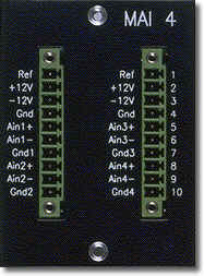
Signal Description
|
Pin |
Signal |
I/O |
Description |
| L-1 | Ref | V Out |
Not available |
| L-2 | +12 V | V Out |
+12 VDC voltage source |
| L-3 | -12 V | Gnd |
-12 VDC voltage source |
| L-4 | Gnd | In | Ground for pins L1 .. L3 |
| L-5 | AIn1+ | In | Analog input, channel 1 positive |
| L-6 | AIn1- | In | Analog input, channel 1 negative |
| L-7 | Gnd1 | In | Ground for channel 1 |
| L-8 | AIn2+ | In | Analog input, channel 2 positive |
| L-9 | AIn2- | In | Analog input, channel 2 negative |
| L-10 | Gnd2 | In | Ground for channel 2 |
| R-1 | Ref | Not available | |
| R-2 |
+12 V |
V Out |
+12 VDC voltage source |
| R-3 | -12 V |
V Out |
-12 VDC voltage source |
| R-4 |
Gnd |
Gnd | Ground for pins L1 .. L3 |
| R-5 | AIn3+ |
In | Analog input, channel 3 positive |
| R-6 | AIn3- |
In | Analog input, channel 3 negative |
| R-7 | Gnd3 |
In | Ground for channel 3 |
| R-8 |
AIn4+ |
In | Analog input, channel 4 positive |
| R-9 | AIn4- | In | Analog input, channel 4 negative |
| R-10 | Gnd4 | In | Ground for channel 4 |
Pin designations: L = left-hand row R = right-hand row
back | Fox Series | Download | Home
Copyright © 2000 TRS
Fieldbus Systems, Inc. All rights reserved.
Revised: August 07, 2000
.