I/O-Modules
Fox Series
Interbus - Coupler
Product Description
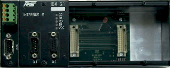
The IBX21 is a Basemodule with a Interbus coupler which can fit up to 4 submodules.
| Submodules | Description | Slot 1 | Slot 2 | Slot 3 | Slot 4 |
| MDI-8 | 8 digital inputs | No | Yes | Yes | Yes |
| MDO-8 | 8 digital outputs, 24V/0.5 A | No | Yes | Yes | Yes |
| MDM-8 | 8 digital outputs, 24V/2.0 A | No | Yes | Yes | Yes |
| MAC-8 | 8 digital inputs, 110/220 V AC | No | Yes | Yes | Yes |
| MDR-8 | 8 relays | No | Yes | Yes | Yes |
| MDIO-16 Out | 16 digital outputs | Yes | Yes | Yes | Yes |
| MDIO-16 In | 16 digital inputs | Yes | Yes | Yes | Yes |
| MDIO-16 8I/8O | 8 digital inputs and 8 digtial outputs | Yes | Yes | Yes | Yes |
| MAI-4 | 4 analog inputs, resolution: 12/16 bits | Yes | Yes | Yes | Yes |
| MAO-4 | 4 analog outputs, resolution: 16 bits | Yes | Yes | Yes | Yes |
| MSSI-2 | 2 synchronous serial interfaces | Yes | Yes | Yes | Yes |
| MINC-2 | 2 incremental encoders | Yes | Yes | Yes | Yes |
| MHAS-2 | 2 HAS encoders | Yes | Yes | Yes | Yes |
| HPWM-2 | 2 pulse width modulation outputs, 24V/2.0A | Yes | Yes | Yes | Yes |
Power Supply
You connect the power supply for the control logic via the four pin connector terminal X10 on the upper left side of the module.
| Pin | Signal | Description |
| 1 | DO1 | + Data line IN, incoming |
| 2 | DI1 | + Data line OUT, outgoing |
| 3 | GNDI | GND incoming interface |
| 4 | NC | reserved |
| 5 | NC | reserved |
| 6 | /DO1 | - Data line IN, incoming |
| 7 | /DI1 | + Data line OUT, outgoing |
| 8 | NC | reserved |
| 9 | NC | reserved |
Connector X2, INTERBUS remote input (D-SUB female, 9 pin)
| Pin | Signal | Description |
| 1 | DO1 | + Data line IN, incoming |
| 2 | DI1 | + Data line OUT, outgoing |
| 3 | GND | GND incoming interface |
| 4 | NC | reserved |
| 5 | NC | +5 V |
| 6 | /DO2 | - Data line IN, incoming |
| 7 | /DI2 | + Data line OUT, outgoing |
| 8 | NC | reserved |
| 9 | NC | reserved |
Note:
If
the remote bus
output is occured
(further INTERBUS device), pin 9 must be connected with pin 5.
Corresponding of the INTERBUS S-specification the status of the module is indicated with the following LED'S:
| LED | Color | Description |
| CC | green |
Cable Check |
| BA | green | Bus Active Lights up if the INTERBUS-watchdog is not active |
| RD | red | Remotebus
Disable Lights up if the subsequent fieldbus is turned off. Is active in the state INTEBUS-RESET. |
| TR | green | Transimt
/ Receive Lights up if this device operates PCB communication (not available in this module) |
| VCC | green | Voltage supply monitoring |
Address & Baudrate will be set automatically by the INTERBUS-S master.
Assembly
You mount the INTERBUS-S base module off-center of the machine or in the control cabinet by simply fastening it to a device mounting DIN rail.
Technical
Data
| Inputs/Outputs |
Max. of 24 digital
I/Os or max. of 16 analog I/Os, 8 SSIs, 8 incremental encoders, 8
HAS encoders, 8 PMW outputs or a mixture of galvanically decoupled
submodules (max. of 4). |
|
Input Specifications |
see input modules for IBX-21 |
|
Output
Specifications |
see output modules for IBX-21 |
|
Output Monitoring |
Watchdog circuit |
|
MDO8 |
INTERBUS, 9 pin SUB-D male and female connector |
| Interface | 2-wire remote bus for INTERBUS-S, RS 422 with galvanic separation, binary |
| Ident. number | 03H |
| Transfer Rate | 300 kbaud net; 500 kbaud gross (inclusive control and status byte) |
|
Supply Voltage |
24 VDC (±
20%) |
|
Current Consumption |
approx. 0.1 A
(without submodules) |
|
Housing |
closed, can be screw-mounted on a device mounting rail complying with DIN EN 50022, 50035 |
|
Dimensions (W x H x
D) |
315 * 76 * 68 mm |
|
Weight |
approx.. 750 g |
|
Operating
Temperature |
±0..+55 °C |
|
Storage Temperature |
-20..+70 °C |
back | Fox Series | Download | Home
Copyright © 2000 TRS
Fieldbus Systems, Inc. All rights reserved.
Revised: August 08, 2000
.