I/O-Modules
Fox Series
Lightbus - Coupler
The
TRS Fiber Optic Industrial Input/Output System, which is referred to as
the FO-II/O system to save space, consists of an intelligent central
module and an optical waveguide-based field bus. The TR-Fieldbus Systems
Industrial Input/Output System is a universal input/output system for
industrial control technology.
Depending
on the system (PC/AT, SMP, AMS, AT96, VME, SIMATIC, Mitsubishi etc.), the
link between the FO-II/O system and the host is implemented by means of a
Logic Cell Array. This guarantees fast, convenient communications. Various
FO-II/O peripheral modules are available for processing the process image.
These modules are connected together in a ring structure.
By
contrast with other types of communication, which are based on
handshaking, in a fiber optic ring only the central unit is active and the
other input and output modules that are connected in the ring are passive.
This makes possible rapid data communication with these modules.
Data
transfer on the optical waveguide is specified by a communications
protocol that is optimized for speed and simplicity. This type of
communication means that the message that the central unit transmits is
received by each module, which interprets it and passes it on with a delay
of approximately 1.5 µs. With a wavelength of 660 nm, the fiber
optic-bus achieves a maximum transfer rate of 6 Mbps. The system that
TRS Fieldbus Systems uses has a transfer rate of 2.5 Mbps; in this
connection, the entire transfer time of 25 µs is needed for one
32-bit message. This means that with a central unit connected to ten
modules, the system triggers and updates all the modules in approximately
300 µs. The central module detects any faults that may occur in the
fiber optic ring and reports them to the host system. The implemented ring
diagnostics functions then make possible rapid troubleshooting and removal
of faults.
The
central module controls communication in the fiber optic ring. It
transmits messages that run through the individual modules in the fiber
optic ring and finally receives them again and checks them.
The use of optical waveguides provides significant advantages compared with conventional copper cabling:
-
High transfer capacity
-
Low signal attenuation
-
No electromagnetic disturbances
-
Potential freedom
-
Low weight
Fox-10
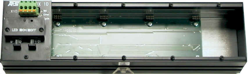
Fox-10
Base Module fitted with three Input and one Output Submodules
The
Fox-10 is a cost effective input/output module. It fits only digital input
/ output submodule. This is most times used if you need 32 or less I/O
points.
| Submodules | Description | Slot 1 | Slot 2 | Slot 3 | Slot 4 |
| MDI-8 | 8 digital inputs | Yes | Yes | Yes | Yes |
| MDO-8 | 8 digital outputs, 24V/0.5 A | Yes | Yes | Yes | Yes |
| MDM-8 | 8 digital outputs, 24V/2.0 A | Yes | Yes | Yes | Yes |
| MAC-8 | 8 digital inputs, 110/220 V AC | Yes | Yes | Yes | Yes |
| MDR-8 | 8 relays | Yes | Yes | Yes | Yes |
| MDIO-16 Out | 16 digital outputs | No | No | No | No |
| MDIO-16 In | 16 digital inputs | No | No | No | No |
| MDIO-16 8I/8O | 8 digital inputs and 8 digtial outputs | No | No | No | No |
| MAI-4 | 4 analog inputs, resolution: 12/16 bits | No | No | No | No |
| MAO-4 | 4 analog outputs, resolution: 16 bits | No | No | No | No |
| MSSI-2 | 2 synchronous serial interfaces | No | No | No | No |
| MINC-2 | 2 incremental encoders | No | No | No | No |
| MHAS-2 | 2 HAS encoders | No | No | No | No |
| MPWM-2 | 2 pulse width modulation outputs, 24V/2.0A | No | No | No | No |
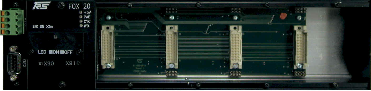
Fox-20
Base Module with one analog input, one analog output,
one digital input and one digital output submodule
The Fox-20 base module is used if you have a high density of digital I/O points (up to 64), any analog, any position or pulse with modulation submodules.
| Submodules | Description | Slot 1 | Slot 2 | Slot 3 | Slot 4 |
| MDI-8 | 8 digital inputs | No | Yes | Yes | Yes |
| MDO-8 | 8 digital outputs, 24V/0.5 A | No | Yes | Yes | Yes |
| MDM-8 | 8 digital outputs, 24V/2.0 A | No | Yes | Yes | Yes |
| MAC-8 | 8 digital inputs, 110/220 V AC | No | Yes | Yes | Yes |
| MDR-8 | 8 relays | No | Yes | Yes | Yes |
| MDIO-16 Out | 16 digital outputs | Yes | Yes | Yes | Yes |
| MDIO-16 In | 16 digital inputs | Yes | Yes | Yes | Yes |
| MDIO-16 8I/8O | 8 digital inputs and 8 digtial outputs | Yes | Yes | Yes | Yes |
| MAI-4 | 4 analog inputs, resolution: 12/16 bits | Yes | Yes | Yes | Yes |
| MAO-4 | 4 analog outputs, resolution: 16 bits | Yes | Yes | Yes | Yes |
| MSSI-2 | 2 synchronous serial interfaces | Yes | Yes | Yes | Yes |
| MINC-2 | 2 incremental encoders | Yes | Yes | Yes | Yes |
| MHAS-2 | 2 HAS encoders | Yes | Yes | Yes | Yes |
| MPWM-2 | 2 pulse width modulation outputs, 24V/2.0A | Yes | Yes | Yes | Yes |
Power Supply
You connect the power supply for the control logic via the four pin connector terminal X10 on the upper left side of the module.
Connector X10:
| Pin | Signal | Description |
| 1 | +24 V logic | Control voltage supply |
| 2 | GND logic | Ground of logic |
| 3 | +24 V logic | Control voltage supply |
| 4 | GND logic | Ground of logic |
Connector X90 / X91:
| Pin | Signal | Description |
| X90 | FO-OUT | Fiber optic ring OUTPUT |
| X91 | FO-IN | Fiber optic ring INPUT |
Three LEDs provide information about the status of the module:
Power LED Base Module (+5V only Fox-20)
| LED | Description |
| OFF | No Power, check Power at X10 connector |
| Orange | Power On |
Error LED (Error (Fox-10) or (PAE) Fox-20)
| LED | Description |
| OFF |
Messages OK (No Error) |
| Red |
Faulty messages, ckeck cable |
Cycle LED (CYC)
| LED | Description |
| OFF | No messages are send, check master |
| Green | Shows message traffic |
Watchdog
| LED | Description |
| OFF | The module receives no write message |
| Light Green | Watchdog is triggered on each output message |
You mount the DeviceNet base module off-center of the machine or in control cabinet by simply fastening it to a device mounting DIN rail.
Setting the Transmission Power
In the LED connection cap, there is a rotary switch that you can turn from outside using a small screwdriver. A green LED shows the switch setting: if the LED is lit up, the transmission power is set to 10 m .. 45 m with plastic cable or 60 ..300m with glass fiber cble; otherwise, the system runs at a power reduced by 4 dB with fiber optic cable lengths of 0.2 m .. 15 m.
Technical
Data
| Inputs/Outputs |
Max. of 32 digital
I/Os or max. of 16 analog I/Os, or a mixture of both via up to
four galvanically decoupled submodules. |
|
Input Specifications |
Refer to input modules for FOX-10/FOX-20 |
|
Output
Specifications |
Refer to output modules for FOX-10/FOX-20 |
|
Output Monitoring |
Watchdog circuit |
| Connections | Toshiba PCS Fiber Optic System or APS Fiber |
|
Data Connection |
Fiber Optic Ring II/O System |
| Transfer Rate | 2.5 Mbps, 25 µs for 32 bits |
|
Supply Voltage |
24 VDC (±
20%) |
|
Current Consumption |
approx. 0.1 A
(without submodules) |
|
Housing |
closed, can be screw-mounted on a device mounting rail complying with DIN EN 50022, 50035 |
|
Dimensions (W x H x
D) |
FOX-10:
305 * 76 * 68 mm FOX-20: 315 * 76 * 68 mm |
|
Weight |
approx.. 750 g |
|
Operating
Temperature |
±0..+55 °C |
|
Storage Temperature |
-20..+70 °C |
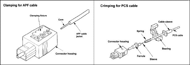
Two base types of
fiber optic cable are available, i.e. all plastic fiber, APF and plastic
cladding silica fiber, PCS. You can lay both types on a trailing cable
chain, since the varying load meets the requirements. The fiber optic
cable transmission and reception chips are designed for APF as well as PCS
cables. APF cables guarantee safe data transmission up to 45 meters; with
PCS cables, this distance is 300 meters. Using special transmission chips
with PCS cables, you can achieve distances of up to 1000 meters.
PCS cables need different connectors from APF cables, however the II/O modules are identical (up to 300 meters). In addition, you need special tools for PCS cables.
You can use a
measuring instrument to measure the attenuation of the cable or of the
connector.
The II/O modules
are connected to the bus link via fiber optic plug-in connectors X90 and
X91 as shown in figure 2.
Preparing
the Fiber Optic Connector
It is quite easy to
prepare the fiber optic connector on the APF cable. First of all, you
strip about 25 mm of the 6-mm polyurethane jacket and cut off the Kevlar
strain relief appropriately without damaging the black internal sheath.
After this, strip 7 mm of the black internal sheath using a cable stripper
or a special cable-stripping tool. Under no circumstances must you damage
the transparent fiber while doing this. Ensure that the cut surface of the
fiber does not split. By feeding in red light at the other end of the
fiber, you can check the end of the fiber. You then push the fiber from
the back all the way in to the connector and then push in the clamping
fixture in to the connector using a screwdriver or similar tool. After
this, sand the end of the fiber that is sticking out of the connector at
right angles to the connector; to do this, first use 600 grain and then
1000 grain emery paper. You must not sand the connector itself. Do not use
any chemical-based polishing pastes, as they harden the fiber. It is
sensible to use a magnifying glass to check the results.
back | Fox Series | Download | Home
Copyright © 2000 TRS
Fieldbus Systems, Inc. All rights reserved.
Revised: August 08, 2000
.