I/O-Modules
Fox Series
Profibus - Coupler
Product Description
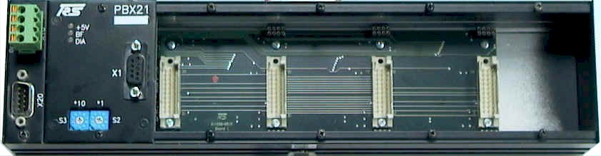
The PBX21 is a Basemodule with a Profibus coupler which can fit up to 4 submodules.
| Submodules | Description | Slot 1 | Slot 2 | Slot 3 | Slot 4 |
| MDI-8 | 8 digital inputs | No | Yes | Yes | Yes |
| MDO-8 | 8 digital outputs, 24V/0.5 A | No | Yes | Yes | Yes |
| MDM-8 | 8 digital outputs, 24V/2.0 A | No | Yes | Yes | Yes |
| MAC-8 | 8 digital inputs, 110/220 V AC | No | Yes | Yes | Yes |
| MDR-8 | 8 relays | No | Yes | Yes | Yes |
| MDIO-16 Out | 16 digital outputs | Yes | Yes | Yes | Yes |
| MDIO-16 In | 16 digital inputs | Yes | Yes | Yes | Yes |
| MDIO-16 8I/8O | 8 digital inputs and 8 digtial outputs | Yes | Yes | Yes | Yes |
| MAI-4 | 4 analog inputs, resolution: 12/16 bits | Yes | Yes | Yes | Yes |
| MAO-4 | 4 analog outputs, resolution: 16 bits | Yes | Yes | Yes | Yes |
| MSSI-2 | 2 synchronous serial interfaces | Yes | Yes | Yes | Yes |
| MINC-2 | 2 incremental encoders | Yes | Yes | Yes | Yes |
| MHAS-2 | 2 HAS encoders | Yes | Yes | Yes | Yes |
| HPWM-2 | 2 pulse width modulation outputs, 24V/2.0A | Yes | Yes | Yes | Yes |
Power Supply
You connect the power supply for the control logic via the four pin connector terminal X10 on the upper left side of the module.
| Pin | Signal | Description |
| 1 | ||
| 2 | ||
| 3 | L2_B | Profibus B |
| 4 | L2_RTS | RTS |
| 5 | L2_GND | Ground |
| 6 | L2_+5V | +5V |
| 7 | ||
| 8 | L2_A | Profibus A |
| 9 |
Three LEDs provide information about the status of the module:
Power LED(+5V)
| LED | Description |
| OFF | No Power - Module (Connector X10) |
| Green | Power OK |
Bus LED (BF)
| LED | Description |
| Green | Profibus Ok |
| Red |
Profibus
Error, |
Diagnostic
| LED | Description |
| Green | Module Ok |
| Red | Diagnostic data present |

Profibus Address
The Profibus adress is
set by two rotary switch (S3 and S2) on the Buscoupler
Example: Address 34
S3 = 3
S2 = 4
Profibus Baudrate
The Profibus coupler detects automatically the Baudrate from 9.6 Kbaud to 12 Mbaud.
Assembly
You mount the Profibus base module off-center of the machine or in the control cabinet by simply fastening it to a device mounting DIN rail.
Technical
Data
| Inputs/Outputs |
Max. of 24 digital
I/Os or max. of 16 analog I/Os, |
|
Input Specifications |
See output modules for PBX-21 |
|
Output
Specifications |
See output modules for PBX-21 |
|
Output Monitoring |
Watchdog circuit |
|
Data Connection |
Profibus DP, 9-pin SUB-D male connector |
| Transfer Rate | Maximum of 12 Mbps |
|
Supply Voltage |
24 VDC (±
20%) |
|
Current Consumption |
approx. 0.1 A
(without submodules) |
|
Housing |
closed, can be screw-mounted on a device mounting rail complying with DIN EN 50022, 50035 |
|
Dimensions (W x H x
D) |
315 * 76 * 68 mm |
|
Weight |
approx.. 750 g |
|
Operating
Temperature |
±0..+55 °C |
|
Storage Temperature |
-20..+70 °C |
back | Fox Series | Download | Home
Copyright © 2000 TRS
Fieldbus Systems, Inc. All rights reserved.
Revised: August 08, 2000
.