I/O-Modules
Fox Series
MINC-2, (Incremental
Counter Interface) Sub module
The MINC-2 input module is a submodule, which is galvanically decoupled by means of optocouplers, for the base module. The submodule provides two incremental counters.
For operation in the I/O system, you can install up to four MINC-2s in the four slots of a base module. This makes possible a maximum of 8 incremental-inputs per base module. In addition, you can combine MINC-2s with different modules, e.g. digital outputs.
|
Technical data |
MINC-2 |
|
Inputs |
Two
incremental counter inputs |
|
Input Level |
Input voltage RS-422 |
|
Resolution |
24-bit counter ( twos complement ) |
|
Encoder Feed |
+5V DC |
|
Current Consumption |
0.1 A (without encoder ) |
|
Housing |
Module with front panel is mounted in the CNX21 using two screws. |
|
Dimensions (WxHxD) |
58 * 72 * 50 mm |
|
Weight approx. |
100 g |
|
Operating temperature |
0°C ... +55°C |
|
Storage temperature |
-20°C ... +70°C |
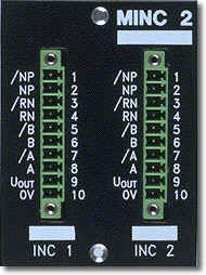
Signal Description
|
Pin |
Signal |
I/O |
Description
of Channel 1 |
| L-1 | /NP | Clock - |
Inv. Zero pulse |
| L-2 | NP | Clock + |
Zero pulse |
| L-3 | RN- | Data + |
Inv. reference cams |
| L-4 | RN+ | Data - |
Reference cams |
| L-5 | /B | Inv. Channel B | |
| L-6 | B | Channel B | |
| L-7 | /A | Inv. Channel A | |
| L-8 | A | Channel A | |
| L-9 | +5 V | Supply | Supply voltage for encoder |
| L-10 | 0 V | Ground | |
|
Pin |
Signal |
I/O |
Description
of Channel 2 |
| R-1 | /NP | Clock - |
Inv. Zero pulse |
| R-2 | NP | Clock + |
Zero pulse |
| R-3 | RN- | Data + |
Inv. reference cams |
| R-4 | RN+ | Data - |
Reference cams |
| R-5 | /B | Inv. Channel B | |
| R-6 | B | Channel B | |
| R-7 | /A | Inv. Channel A | |
| R-8 | A | Channel A | |
| R-9 | +5 V | Supply | Supply voltage for encoder |
| R-10 | 0 V | Ground |
Pin designations: L = left-hand row R = right-hand row
back | Fox Series | Download | Home
Copyright © 2000 TRS
Fieldbus Systems, Inc. All rights reserved.
Revised: August 07, 2000
.