I/O-Modules
Fox Series
MPWM-2, PWM (Pulse
Width Modulation) Sub module
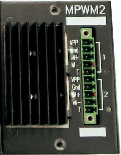
The MPWM-2 pulse width modulation module is a submodule, which is galvanically decoupled by means of optocouplers, for the base module. The submodule provides two PWM interfaces.
For operation in
the I/O system, you can install up to four MPWM-2s in the four slots of a base module. This makes possible a maximum of 8 PWM outputs per
base module. In addition, you can combine MPWM-2s with different modules, e.g.
digital outputs.
The MPWM-2 module is a submodule for the Fox series. This module can control two motors by means of pulse width modulation. The maximum output voltage is 30V and the current is a maximum of 3A.
|
Male Connector |
MPWM-2 |
|
VPP1: |
+ Pos. supply voltage of driver chip for motor 1 (max. of 30V) |
|
GND1: |
- Neg. supply voltage of driver chip for motor 1 |
|
M1+: |
+ Pos. connection of motor 1 |
|
M1-: |
- Neg. connection of motor 1 |
|
T1: |
Connection
not used LED lights up on overtemperature of driver of motor 1. |
|
VPP2: |
+ Pos. supply voltage of driver chip for motor 2 (max of 30V) |
| GND2: | - Neg. supply voltage of driver chip for motor 2 |
|
M2+: |
+ Pos. connection of motor 2 |
|
M2-: |
- Neg. connection of motor 2 |
|
T2: |
Connection
not used LED lights up on overtemperature of driver of motor 2. |
Mark to Space Ratio
You set the mark to
space ratio by means of a twos complement representation with a resolution
of ±9-bit (±512) + 1 sign bit. These 10-bits are arranged left-justified
in the 16-bit-word. The bottom six bits are meaningless.
8000H
100% mark (negative direction of rotation)
0H 0%
mark
7FF0H 100% mark (positive direction of rotation)
You can set the space in
16 steps. The shortest space is 25.6ms and the longest one is 0.84s.
Bit 0-3: Setting the space
|
Decimal
Value |
Space | Clock Frequency |
| 0 | 839 ms | 1.19 Hz |
| 1 | 419 ms | 2.38 Hz |
| 2 | 210 ms | 4.77 Hz |
| 3 | 105 ms | 9.54 Hz |
| 4 | 52.4 ms | 19.1 Hz |
| 5 | 26.2 ms | 38.1 Hz |
| 6 | 13.1 ms | 76.3 Hz |
| 7 | 6.55 ms | 152 Hz |
| 8 | 3.28 ms | 304 Hz |
| 9 | 1.64 ms | 610 Hz |
| 10 | 819.2 ms | 1.2 kHz |
| 11 | 409.6 ms | 2.4 kHz |
| 12 | 204.8 ms | 4.9 kHz |
| 13 | 102.4 ms | 9.8 kHz |
| 14 | 51.2 ms | 19.5 kHz |
| 15 | 25.6 ms | 39.1 kHz |
Structure of Command Byte
| Bit | Description |
| 0 | 0: Off
Mark 0% (Transistors are short-circuited) 1: On The set mark is output |
| 1 | 0: Brake on (transistors
are short-circuited) 1: Brake off |
| 2 | 0:
Free-wheeling on (transistors are high-resistance) 1: Free-wheeling off |
Free-wheeling,
brake and on/off have the following priorities:
Free-wheeling has the highest priority and on/off the lowest. If all the
bits are 0, for example, free-wheeling is active, since it has the highest
priority.
Structure of Status
byte
| Bit | Description |
| 0 | 0: Off
Mark 0% 1: On The set mark is output |
| 1 | 0: Brake on (transistors
are short-ciruited) 1: Brake off |
| 2 | 0: Free
wheeling on (transistors are high-resistance; PWM-bit = 0 and brake-bit 1 ) 1: Free-wheeling off |
| 3-6 | Not assigned |
| 7 | 0:
Temperature of motor component is ok 1: Temperature of motor component is too high. |
back | Fox Series | Download | Home
Copyright © 2000 TRS
Fieldbus Systems, Inc. All rights reserved.
Revised: August 30, 2000
.