I/O-Modules
Fox Series
MDIO16-16O, Digital
Output Sub-module
The MDIO16-16O output module is a submodule, which is galvanically decoupled by means of optocouplers, for the base module. The submodule can provide 16 outputs for 24V/0.5A. For operation in the I/O system, you can install up to four MDIO16-16Os in the four slots of a base module. This makes possible a maximum of 64 digital I/O’s per base module. In addition, you can combine MDIO16-16Os with different modules, e.g. digital inputs.
For a different Input/Output combination ( for example 12 Input and 4 Output) please contact our technical team.
|
Technical data |
MDIO16-16O |
|
Outputs |
Outputs,
galvanically decoupled. LED output status indicators LED voltage indicator |
|
Output Specifications |
24V
/ 0.5A short-circuit -proof After getting rid of an existing short-circuit, the output resets itself to its logical status, i.e. if the output is set from the point of view of the message, it switches ON. |
|
Supply Voltage |
24 VDC (± 20%) |
|
Current consumption |
0.05 A (without load and input currents) |
|
Housing |
Module with front panel is mounted in the CNX21 using two screws. |
|
Dimensions (WxHxD) |
58 * 72 * 50 mm |
|
Weight approx. |
100 g |
|
Operating temperature |
0°C ... +55°C |
|
Storage temperature |
-20°C ... +70°C |
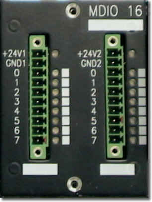
Signal Description
|
Pin |
Signal |
I/O |
Description |
| L-1 | +
24V |
VCC |
+ 24
VDC output
driver supply |
| L-2 | 0V | GND |
Ground, feedback of outputs |
| L-3 | DI
0 |
Output |
Bit 0 of data bytes |
| L-4 | DI 1 |
Output | Bit 1 of data bytes |
| L-5 | DI
2 |
Output | Bit 2 of data bytes |
| L-6 | DI 3 |
Output | Bit 3 of data bytes |
| L-7 | DI
4 |
Output | Bit 4 of data bytes |
| L-8 | DI 5 |
Output | Bit 5 of data bytes |
| L-9 | DI
6 |
Output | Bit 6 of data bytes |
| L-10 | DI 7 |
Output | Bit 7 of data bytes |
| R-1 | +24V |
VCC |
+ 24 VDC output driver supply |
| R-2 |
0V |
GND |
Ground, feedback of outputs |
| R-3 | 0V |
Output | Bit 8 of data bytes |
| R-4 |
0V |
Output | Bit 9 of data bytes |
| R-5 | 0V |
Output | Bit 10 of data bytes |
| R-6 | 0V |
Output | Bit 11 of data bytes |
| R-7 | 0V |
Output | Bit 12 of data bytes |
| R-8 |
0V |
Output | Bit 13 of data bytes |
| R-9 | 0V |
Output | Bit 14 of data bytes |
| R-10 |
0V |
Output | Bit 15 of data bytes |
Pin designations: L = left-hand row R = right-hand row
back | Fox Series | Download | Home
Copyright © 2000 TRS
Fieldbus Systems, Inc. All rights reserved.
Revised: August 08, 2000
.