I/O-Modules
Fox Series
MDM-8, Digital Power
Output
Sub-module
The MDM-8 output module is a submodule, which is galvanically decoupled by means of optocouplers, for the CNX21 base module. The submodule provides eight digital outputs for 24V/2.2A. For the operation in the II/O system, you can install up to four MDM-8’s in the four slots of a CNX21 base module. This makes possible a maximum of 32 outputs per CNX21. In addition, you can combine MDM-8’s with different modules, e.g. digital inputs.
The outputs are
short-circuit-proof and protected against thermal overload. For inductive
loads, the outputs are protected by an avalanche diode rated at
72V/5A/100mJ. Due to the high avalanche voltage, the break-time of an
inductive load is very low (typically less than 30 ms).
|
Technical data |
MDM-8 |
|
Outputs |
8
switching outputs, galvanically decoupled 2 error outputs 8 LED output status indicators 2 LED error indicators 1 LED voltage indicator |
|
Output Specifications |
24V
/ 2.2A (*1),
short-circuit proof, thermally protected suitable for inductive loads (*2), RDSon = 100 mOhm |
|
Output Monitoring |
Watchdog
Circuit 2 error outputs, 24V / 10mA, short-circuit-proof |
|
Supply Voltage |
24 VDC (± 20%) |
| Current Consumption | System
voltage: 20 mA Switching voltage: 80 mA (without load currents) |
|
Housing |
Module with front panel is mounted in the CNX21 using two screws |
|
Dimensions (WxHxD) |
58 * 72 * 50 mm |
|
Weight approx. |
200 g |
|
Operating temperature |
0°C ... +55°C |
|
Storage temperature |
-20°C ... +70°C |
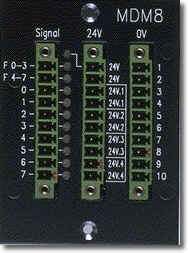
Signal Description
|
Pin |
Signal |
I/O |
Description |
| L-1 | F
0-3 |
Out |
Error output for channels 0-3 |
| L-2 | F 4-7 | Out |
Error output for channels 4-7 |
| L-3 | DO
0 |
Out |
Bit
0 of data byte 0, 1, 2 or 3 |
| L-4 | DO 1 |
Out | Bit 1 of data byte 0, 1, 2 or 3 |
| L-5 | DO
2 |
Out | Bit
2 of data byte 0, 1, 2 or 3 |
| L-6 | DO 3 |
Out | Bit 3 of data byte 0, 1, 2 or 3 |
| L-7 | DO
4 |
Out | Bit
4 of data byte 0, 1, 2 or 3 |
| L-8 | DO 5 |
Out | Bit 5 of data byte 0, 1, 2 or 3 |
| L-9 | DO
6 |
Out | Bit
6 of data byte 0, 1, 2 or 3 |
| L-10 | DO 7 |
Out | Bit 7 of data byte 0, 1, 2 or 3 |
| M-1,
2 |
24V | VCC |
+ 24 VDC logic supply for output stage |
| M-3, 4 | 24V.1 | VCC |
+ 24 VDC supply of outputs bit 0 and bit 1 |
| M-5, 6 | 24V.2 | VCC |
+ 24 VDC supply of outputs bit 2 and bit 3 |
| M-7, 8 | 24V.3 | VCC |
+ 24 VDC supply of outputs bit 4 and bit 5 |
| M-9, 10 | 24V.4 | VCC |
+ 24 VDC supply of outputs bit 6 and bit 7 |
| R-i | 0V |
GND |
ground, feedback of outputs |
| i = 1 to 10 |
Pin designations: L = left-hand row R = right-hand row M = middle-hand row
back | Fox Series | Download | Home
Copyright © 2000 TRS
Fieldbus Systems, Inc. All rights reserved.
Revised: August 07, 2000
.