I/O-Modules
Fox Series
MDR-8, Digital
Output Relay Sub-module
The MDR-8 output module is a submodule, which is galvanically decoupled by means of optocouplers, for the CNX21 base module. The submodule provides eight digital outputs. For operation in the II/O system, you can install up to four MDR-8s in the four slots of a CNX21 base module. This makes possible a maximum of 32 outputs per CNX21. In addition, you can combine MDR-8s with different modules, e.g. digital inputs.
Per output, there
are available on the connectors a normally closed contact, a mid-position
contact and a normally open contact.
To protect the
relay contacts, the system short-circuits the voltage peaks, which occur
at the NO or NC contact when inductive loads switch, via varistors to the
front connectors designated N. The MDR-8 is provided for a 110V switching
voltage. The breakdown voltage of the varistors mentioned above is matched
to the switching voltage. For reasons of interference protection, it is,
however, sensible to directly suppress the interference of inductive
consumers.
If the MDR-8 is
used to switch 110V, you must connect the protective earth to the
appropriate connection.
The relays used
have a rated test voltage of 3000 VAC and a surge withstand capability of
5000V between the contact and the coil, i.e. between the load current
circuit and the 24V system voltage. If this dielectric strength is
insufficient with 110V applications, relays with greater dielectric
strength are available on request.
Since the relay needs a coil voltage of at least 20V to pick up, the CNX21
operating voltage range is limited to 24V -15% / +20% when the MDR-8 is
being used.
|
Technical data |
MDR-8 |
|
MDR-8 Outputs |
8
relay outputs, galvanically decoupled 8 LED output status indicators 1 LED voltage indicator |
|
Outputs |
NC
(Normally Closed) contact, mid-position contact, NO (Normally Open) contact |
| Relay Data | Switching
voltage:
0.1 - 220V Switching current: 1A Switching cycle: 1*10^5 ...5*10^7 test voltage Contact/coil: 3000VAC impulse voltage Contact/coil: 5000V |
| Contact Protector | Varistor
between NO or NC contact and corresponding N connections Varistor data: Wtm (10/1000us) 0.8J Itm (8/20us) 100A Um (ac) 110V Version 163V 220V Version 253V |
|
Output Monitoring |
Watchdog Circuit |
|
Supply Voltage |
5V/ 0.02 A; 24V / 140 mA (relay coil current) |
| Current Consumption | System
voltage: 20 mA Switching voltage: 80 mA (without load currents) |
|
Housing |
Module with front panel is mounted in the CNX21 using two screws |
|
Dimensions (WxHxD) |
58 * 72 * 50 mm |
|
Weight approx. |
300 g |
|
Operating temperature |
0°C ... +55°C |
|
Storage temperature |
-20°C ... +70°C |
Signal Description
|
Pin |
Signal |
I/O |
Description |
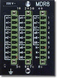
| L-1 | s1 | Out |
NO contact, relay 1 |
| L-2 | m1 | Out |
Mid-position contact, relay 1 |
| L-3 | o1 |
Out |
NC contact, relay 1 |
| L-4 | s2 | Out | NO contact, relay
2 |
| L-5 | m2 | Out | Mid-position
contact, relay 2 |
| L-6 | o2 | Out | NC contact, relay
2 |
| L-7 | s3 | Out | NO
contact, relay 3 |
| L-8 | m3 | Out | Mid-position
contact, relay 3 |
| L-9 | o3 | Out | NC
contact, relay 3 |
| M-1 |
s4 | Out |
NO contact, relay 4 |
| M-2 | m4 | Out |
Mid-position contact, relay 4 |
| M-3 | o4 | Out |
NC contact, relay 4 |
| M-4 | s5 | Out | NO contact, relay 5 |
| M-5 | m5 | Out | Mid-position contact, relay 5 |
| M-6 |
o5 | Out |
NC contact, relay 5 |
| M-7 | s6 | Out | NO contact, relay 6 |
| M-8 | m6 | Out |
Mid-position contact, relay 6 |
| M-9 | o6 | Out | NC contact, relay 6 |
| R-1 | s7 |
Out | NO contact, relay 7 |
| R-2 | m7 |
Out |
Mid-position contact, relay 7 |
| R-3 | o7 |
Out | NC contact, relay 7 |
| R-4 | s8 |
Out | NO contact, relay 8 |
| R-5 | m8 |
Out |
Mid-position contact, relay 8 |
| R-6 | o8 |
Out | NC contact, relay 8 |
| R-7 | N |
Input | Conductor for contact protection, relay 1..3 |
| R-8 | N | Input |
Conductor for contact protection, relay 4..6 |
| R-9 | N | Input |
Conductor for contact protection, relay 7..8 |
Pin designations: L = left-hand row R = right-hand row M = middle-hand row
back | Fox Series | Download | Home
Copyright © 2000 TRS
Fieldbus Systems, Inc. All rights reserved.
Revised: August 07, 2000
.